Abstract
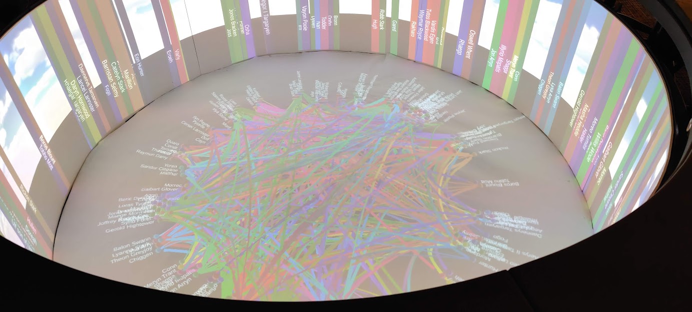
The Campfire is a multi-dimensional display hardware developed by Dr. Ameres to simulate and display unique visualizations. This is a custom visualization tool that parses the total amount of dialogue between a character as a weight and simulating the connection between the relationship between various characters as a dynamic Force Directed Graph constrained to the shape of the display. This visualization includes interactability to see particular connections between various characters.
Technology/Hardware Stack
- Unity 2021 & C#
- Campfire
Introduction
The Campfire is a visualization tool developed by the Rensselaer IDEA in order to demonstrate a multi-user, collaborative environment. [1, 2] Therefore, several ideas including graphs, were proposed to be incorporated into the campfire identity. One of which is a force-directed graph, implemented to suit the specifications of the campfire. This graph algorithm, a force-directed graph, offers dynamic usage and generation [3], with a geometric constraint we are able to reduce the visual complexity of the graph as well as making it suitable for the campfire. This is done by using the edges of the campfire as a constraint.
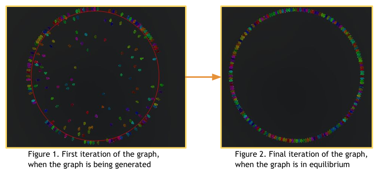
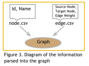
In the figure 1, the nodes are generated in a random location due to the radius of the constraint and in figure 2 the nodes are in equilibrium and constrained to the shape we assign it to (circle). Moreover, the graph parses in information of the nodes and edges given the format of two .csv files. One of which is a file of nodes represented by their ID and name, the second is the node and their target, which makes up an edge, and that edge weight.
In the figure 1, the nodes are generated in a random location due to the radius of the constraint and in figure 2 the nodes are in equilibrium and constrained to the shape we assign it to (circle). Moreover, the graph parses in information of the nodes and edges given the format of two .csv files. One of which is a file of nodes represented by their ID and name, the second is the node and their target, which makes up an edge, and that edge weight.
Abstract Implementation
The graph is generated by parsing in nodes and their relevant connections (edges), for each node there exists a weight, which defines the force pulling a node to another node defined through a spring. Then, we have a constraint that will pull the nodes to a stable equilibrium, which establishes a geometric pattern of nodes. This geometric constraint is the Campfire, with a radius calculated based on the total nodes that would wrap around this constraint. Thus all of the nodes generated would fit in a circular equilibrium with all nodes (spheres) tangent to each other adjacent node. The constraint has a spring force larger than any other weight force in order to forcibly pull the node to that equilibrium.
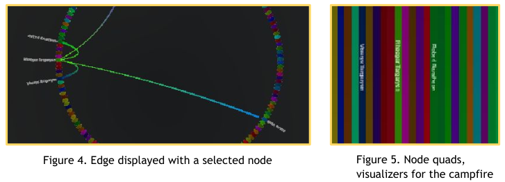
Moreover, we are able to visualize the connections of each node by adding a line that represents an edge. This edge only can be viewed if we select that node and examine its edges, otherwise all edges are hidden for clarity. With the Campfire, every node includes a non-collidable quad that represents an interactable node, this would indicate the node of the node and color in order to make them visually distinct. A possible future implementation would extend these values to depict other qualities of the nodes or connections. The lines are rendered to develop a visualization similar to a chord diagram. [4]
Example
With an implementation of the graph, we are able to demonstrate specific character interactions from the popular book series Game of Thrones, more specifically A Song of Ice and Fire, from author George R.R. Martin. From the dataset provided by Beveridge [5], for each book (1 to 5) and all the books, we are able to generate a constrained force-directed graph, and have it demonstrated on the campfire. Moreover, since the graphs are dynamically generated and loaded, we are able to store the data and generate the graph at runtime in the Campfire. The graph displays adjacent nodes as viewable quads. On each quad, a character’s name is written, and for every connection to the selected node their character is written.
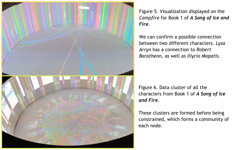
Furthermore, with the capabilities of a game engine, Unity, and the visual platform of the Campfire, it is possible to dynamically construct any graphs given the correct set of data provided the format of the parser.

Implementation
This section is under many constant updates and can variable change over time, consider this part under construction for now. I have included a link of this project below.
Data Parsing
The data provided by the interaction of characters between ASOIAF is given by the edges and nodes. Represented as:
Edges
1 | Source,Target,Type,id,weight |
Nodes
1 | Id,Label |
We can easily extract this data and store it in some arbitrary class for further evaluation, this allows us to obtain the exact values for the minimum and maximum weights we require for the data. Note: The code blocks here do not include all of the fields, functions, etc that makes the implementation function, just think of them like pseudocode. For the full code implementation I have linked a github repo of the partial implementation below.
1 | public class Data { |
Nodes and Edges
Before parsing the data into the graph, it is imperative that we should define the general use cases for the node and edge data that we can parse into that creates the graph. Furthermore, note that we inherit unity’s monobehaviour s.t. it can utilize GameObjects and can be physics objects.
1 | public class Node : MonoBehaviour { |
Graph
Here, all we need to do is to create a dictionary that can abstract all of the data for our use case
1 | Dictionary<string, NodeData> generateNodeDataFromCSV(Data nodes, Data edges){ |
Finally, we can take this generated dictionary of node datas and generate a graph
1 | void generateGraphFromNodeData(Dictionary<string, NodeData> nodeData){ |
Rendering
To show a connection between a node and the edge, we can add a LineRenderer to the edge as well as a spline (for that visual curve).
1 |
|
References
- [1]: E. L. Ameres, “Reducing the cognitive load of visual analytics of networks using concentrically arranged multi-surface projections focusing immersive real-time exploration,” (2018)
- [2]: Campfire. https://patft.uspto.gov/netacgi/nph-Parser?Sect1=PTO2&Sect2=HITOFF&p=1&u=%2Fnetahtml[…]l=50&co1=AND&d=PTXT&s1=ameres.INNM.&OS=IN/ameres&RS=IN/ameres
- [3]: P. Eades, “A heuristic for graph drawing,” Congressus Numerantium, 42, 149–160 (1984)
- [4]: Chord Diagram. https://en.wikipedia.org/wiki/Chord_diagram_(information_visualization)
- [5]: A. Beveridge, “Character Interaction Networks for George R. R. Martin’s “A Song of Ice and Fire” saga” https://github.com/mathbeveridge/asoiaf. (2017)